Reddit user BigReid has posted an update on his PCB based hairpin ADS-B filter. He has now added a low noise amplifier (LNA) circuit onto the same PCB board. BigReid used the LNA design written about on this page. The PCB files are here and the Reddit thread can be found here.
His results show that the LNA works very well. Akos tested the LNA4ALL on multiple frequencies and applications including commercial radio, airband, NOAA weather satellites, AIS and ADSB. As an example of the improvement, his ADSB reception was improved from 83km to 94km. In his review Akos also shows how to provide power to the LNA, and puts the LNA through some simple stress tests.
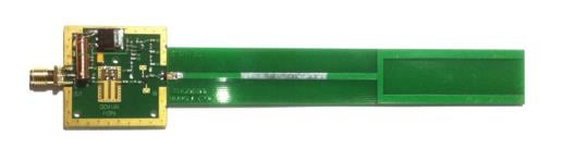
This ADS-B antenna by amateur radio hobbyist F5ANN combines a 30dB LNA preamplifier, bandpass filter and antenna tuned for 1090MHz together on a single PCB board. The LNA preamplifier helps boost weak signals, whilst the bandpass filter helps to remove interference from others signals such as GSM. The novel thing about this antenna is that everything is neatly packaged into a single PCB board, which makes this antenna very compact, and yet have high performance.
F5ANN uses his combined antenna together with an RTL-SDR dongle and the RTL 1090 ADS-B decoding software with PlanePlotter, and was able to receive 194 simultaneous aircraft signals with a message rate of 556 messages a second at distances of up to 250 nm.
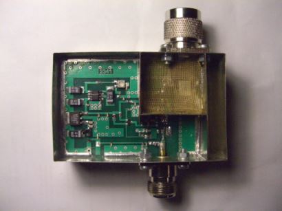
At the center of his system is an LNA with 40dB gain and a very low noise figure of 0.2dB. This LNA appears to be based on G4DDK’s VLNA, but modified to work with the 1420 MHz frequency used for radio astronomy. It seems the LNA can be ordered for 140 USD from the above link.
Note: The above Russian links are machine translated with Google to English.
Back in November last year we posted about the possibility of an “LNA4HF” low noise amplifier (LNA) for the HF bands being made available for sale. The LNA4HF is now available for purchase.
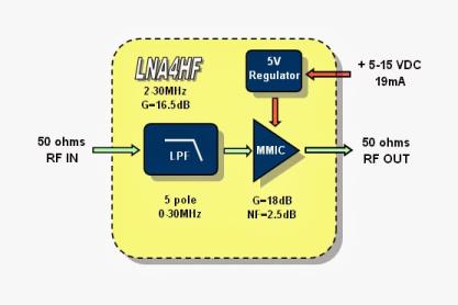
The LNA4HF is a low noise amplifier with built in low pass filter that runs on a 6-12 V power supply and covers a frequency range of 150khz to 30MHz, with a 18-20 dB gain and 1-2 dB noise figure. It costs 20 Euros. The low pass filter can also be disabled with a small board modification which will allow the amplifier to be useful at up to 2 GHz.
LNA4HF
LNA4HF Block Diagram
Akos from the SDR for Mariners blog has reviewed the LNA4HF on his latest post. His results show that the low pass filter significantly reduces broadcast FM interference and that the amplifier also increases signal strength by around 20 dB as advertised.
Over on Reddit user soooooil has posted about his work in building an LNA, including etching the PCB. On his imgur page he shows the design and construction process through images, before showing the final result in SDR#. For the LNA he used a ERA-3SM+ MMIC which has 17-23 dB of gain and a NF of 2.6-2.8 dB. While the noise figure is fairly high for an LNA, it is still likely lower than the RTL-SDRs internal amplifier noise figure which is around <4.5 dB.
The antenna was created by F5ANN, and he used his active antenna together with an RTL-SDR dongle, the RTL1090 ADS-B decoding software and PlanePlotter, and was able to receive 194 simultaneous aircraft signals with a message rate of 556 messages a second at distances of up to 250 nm.
This antenna can now be bought from the 1090mhz.com webstore, and is available with or without LNA. The LNA will help if you need long runs of coaxial cable between the antenna and RTL-SDR.
Over on YouTube Adam, the creator of the LNA4ALL, LNA4HF and UP100 upconverter has uploaded a video showing that the noise that is produced by the RTL-SDR dongle itself can degrade performance when combined with an LNA and/or upconverter.
Most commonly we’ve seen people mount the RTL-SDR dongle together with an upconverter and/or LNA in the same shielded box right next to each other. However, these results show that the RTL-SDR should be shielded separately from the LNA and upconverter for best performance.
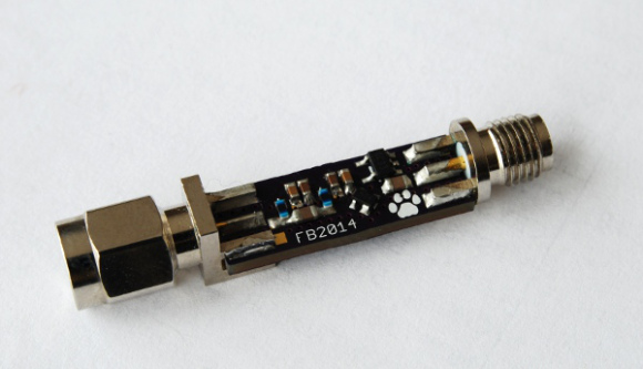
Recently a reader named Fabio wrote in to let us know about his new Low Noise Amplifier (LNA) design for the RTL-SDR. Fabio writes that his design is similar to the LNA4ALL, but is small enough to fit inline with an antenna. An LNA can help improve reception especially if you have long runs of coax cable between the antenna and RTL-SDR.
Fabio’s design requires that the LNA be powered inline with a bias-tee power injector circuit which can be easily built from an inductor and capacitor. But instead of building an external bias-tee he modified the RTL-SDR dongle itself to provide the required 5V output power from the USB bus. He writes that with this modification the RTL-SDR could also be used to power an active antenna.
Japanese blogger and RTL-SDR experimenter ttreftech has had an ADS-B front end kit (In Japanese, use Google Translate) consisting of a low noise amplifier (LNA) and SAW filter available for sale in Japan for a few months now. The LNA helps to push weak signals through the coax feed line and the SAW filter is a bandpass filter that helps to remove interference outside of the 1090 MHz ADS-B region. If you are interested in building your own version, ttrftech has also posted a schematic. Another recent post about the front-end can be found here.
Another Japanese blogger, “pup” has posted about his results with the ADS-B front end kit (Also in Japanese, use Google Translate). His results show that the front end does significantly improve ADS-B reception. The image below shows an ADS-B signal with the front end turned off (top) and with it turned on (bottom). Pup has also posted a video showing the kit and its performance on HDSDR.
Over on YouTube Adam Alicajic the designer of the LNA4ALL low noise amplifier has uploaded a video showing the effect of an LNA on reception of a weak signal. He shows an example of how a very weak signal cannot be received by the RTL-SDR even when the gain is set to maximum unless an LNA is connected.
Adam has posted this video in regards to some statements saying that an LNA will only increase the noise floor and cannot bring signals out of the noise floor. There is a discussion about this on this Reddit thread.
Most wideband SDR’s do not come with any front-end filtering built in. This limits their ability to receive weak signals in the presence of strong signals. Recently Sivan, a reader of RTL-SDR.com wrote in to let us know about a paper he published through the ARRL detailing how to design a concrete front-end unit for SDR use. A front-end helps to filter out signals that are outside of the desired passband, thus reducing interference from nearby strong signals significantly. Although Sivan uses a USRP with WBX daughtercard in his paper, he writes that the same front-end design principals can be applied to the RTL-SDR as well.
In the paper he designs a 431 – 435 MHz front-end using low cost SAW filters, a low noise amplifier (LNA) and a limiter to protect the radio. He writes that the design could easily be adapted for other bands as well.
Using the free AppCAD RF design assistant software, Anthony explains how the noise figure of a system increases with longer coax cable runs, and how it can be reduced by placing an LNA right next to the antenna. He also explains why the sensitivity of the radio won’t increase if the LNA is placed close to the radio instead.
In addition to this, he also explains why adding more LNA’s to a system decreases the linearity (IP3) of the system and that if the receiver has a built in LNA that the system linearity can be severely degraded by adding extra LNA’s, causing easy overloading and intermodulation. In conclusion Anthony writes the following:
In summary, a setup with a good antenna system connected to a receiver with a built in LNA:
May not benefit from having a preamp at the antenna.
The presence of a built in LNA is detrimental to the linearity and may degrade the signals.
So in conclusion:
Put the preamp as close to the antenna as possible.
Receivers with a built in LNA may not get the most out of an antenna system or preamp.
Proper gain distribution guarantees better performance than one-size-fits-all solutions, both in terms of sensitivity and strong signals handling.
Optimal Setup: Antenna -> LNA -> Coax -> ReceiverNF and Linearity Calculations in AppCAD
Over on his blog RTLSDR4Everyone author Akos has uploaded a new post showing what he believes is the best possible RTL-SDR set up that you can get for under $60. Akos writes that the best combination of components is one of our RTL-SDR Blog dongles (back in stock in a couple of weeks!) with bias tee combined with an LNA4ALL low noise amplifier. The LNA4ALL is a ~$30 USD LNA based on the Minicrcuits PSA4-5043+ component and is sold by Adam 9A4QV who also sells other products such as RF filters.
Akos reminds us that the LNA4ALL can actually be bought from Adam with the bias tee enabled already which saves you from the difficulty of needing to source the required inductor and perform surface mount soldering. The post also explains why you might want to use an LNA in the first place and how to enable the bias tee on our RTL-SDR.com dongles.
RTL-SDR.com dongle + an LNA4ALL powered with the bias tee
Recently FlightAware released a new RTL-SDR dongle sold at zero profit at $16.95 USD. It’s main feature is that it comes with an ADS-B optimized low noise amplifier (LNA) built directly into the dongle. FlightAware.com is a flight tracking service that aims to track aircraft via many volunteer ADS-B contributors around the world who use low cost receivers such as the RTL-SDR. In this post we will review their new dongle and hopefully at the same time provide some basic insights to LNA positioning theory to show in what situations this dongle will work well.
FlightAware Dongle Outside
A good LNA has a low noise figure and a high IIP3 value. Here is what these things mean.
Noise Figure
An LNA is generally used in a RX radio system to reduce the overall noise figure (NF). In simple terms, the NF is a metric that measures how much noise (in dB) components such as amplifiers, coax cables and filters are contributing to the system. The overall noise figure is dominated by the first amplifier in the system, and so by adding a low NF amplifier (LNA) right by the antenna, the NF of the entire radio system can be significantly reduced. For example if the total NF of your radio system was 10 dB, and you reduced it to 1 dB by adding in a good LNA by the antenna, then your signal would become 9 dB stronger.
By placing the LNA by the receiver (as what FlightAware have done with their dongle), the benefits of the LNA are limited as the noise figure of components before the LNA like the coax and filters can not be overcome. However, there is still one significant benefit. The noise figure of the R820T/2 chip is advertised at 3.5 dB at maximum gain, but in reality it is more like 6 dB. So by placing a 0.4 dB NF LNA before the R820T2 tuner the overall system noise figure can still be reduced by about 5 dB’s. This means that you will get a 5 dB stronger signal.
However, although the NF is reduced, there is still the problem of there now being potentially too much gain in the system, which may cause the RTL-SDR to overload on out of band signals. Reducing the RTL-SDR gain would increase the NF of the R820T chip, bringing the overall noise figure back to how it was without an LNA – back to square one. Instead of reducing the gain the overloading problem can be eliminated by using a filter, and this is indeed suggested by FlightAware. The filter will remove strong out of band signals, and since ADS-B signals are not very strong there is no chance of in band overloading.
IIP3/OIP3
The IIP3 (third order input intercept point) and OIP3 (third order output intercept point) are measurements for amplifiers that explain how linear they are. The IIP3/OIP3 linearity measurements explain how strong of a signal can be input (or output) before the LNA will saturate and overload, thus causing very poor reception. The OIP3 is simply the IIP3 + the gain of the amplifier. Higher values for the IIP3/OIP3 are better as it means that stronger signals can be received without overloading.
The IIP3/OIP3 of the entire system is reduced as more LNA’s are added. So adding too many LNA’s can cause trouble with overloading. The problem of overloading for ADS-B can easily be overcome by adding in a sharp filter, such as the FA ADS-B filter to block out other very strong signals such as broadcast FM, pagers and GSM. As long as the in band ADS-B signals are not overly strong (which they are not), the system will be fine even with a lower IIP3/OIP3.
If the LNA has a high IIP3/OIP3 value, and is not overloading, then it is optimal to place the LNA first, before any filters, so that the filter insertion loss can be overcome. If the LNA IIP3/OIP3 is low and it is overloading, then place the filter before the LNA to reduce strong out of band signals, or use an attenuator.
The FlightAware dongle advertises an OIP3 of 39 dBm for its built in LNA which is at the high end and so is good. For comparison the popularly used LNA4ALL has a OIP3 of about 33.5 dBm.
Placing the LNA by the Antenna Pro/Cons
The pros and cons of placing an LNA by the antenna are shown below.
Pros
Cons
Can achieve a very low noise figure by overcoming the NF increase caused by the:
R820T tuner
Coax cable
Filters
Switches/Splitters etc.
Is the optimal arrangement for best reception.
Need to place the LNA by the antenna (may be difficult to access).
Needs DC power from a bias tee or other source.
May need weather proofing if placed outdoors.
Placing the LNA by the Receiver Pro/Cons
The pros and cons of placing an LNA by the receiver are shown below.
Pros
Cons
Can overcome the high NF of the R820T tuner.
Easy to implement and cheaper.
Smaller improvement compared to placing the LNA by the antenna.
IIP3/OIP3 will be reduced if another external LNA needs to be used to overcome a long coax cable.
Without filtering the increased gain can cause overloading, requiring that the R820T gain be reduced, increasing it’s NF and thus causing the overall NF to rise again to levels seen without the extra LNA.
Product Review
The dongle itself comes in a good looking and tough orange plastic enclosure. It is flat on the bottom, with a curved topside. There are several ventilation holes on the bottom. It uses an SMA connector for the RF input. It uses an R820T2 chip, but does not come with a TCXO. (A TCXO is not needed for wideband signals like ADS-B). The dongle is made by Newsky who make the majority of RTL-SDR dongles at the moment.
On the inside we can see that most of the dongle remains the same, except for the LNA circuit which can be seen to the top right, near the RF input. The LNA is labelled SKY 7150, which appears to correspond to the Skyworks SKY67150-396LF chip. The specs are 0.3-2.2 GHz operation, with a noise figure (NF) of 0.23 @ 849 MHz and a high OIP3 figure of up to 39 dBm. FlightAware themselves advertise a NF of 0.4 and OIP3 of 39dBm which may be the figures for 1090 MHz. The chip costs about $2.70 USD for volumes of 500 or more.
FlightAware Dongle Circuit
The total current use of the dongle sits at about 330 mA. A regular dongle consumes about 270 mA, so it appears that the LNA is using about 60 mA. This current usage is suspiciously low for a 39 dBm LNA, which should be drawing about 100 mA.
The low current usage can be explained because they are powering the LNA from the 3.3V line and not the 5V line. In the PGA-103+, a similar LNA, using 3V instead of 5V causes a 40mA drop in current usage and about a 8 dBm drop in OIP3 according to the datasheet. The SKY67150 also has adjustable current draw and they may have adjusted the circuit to make it draw less current so that mini PC’s like the Raspberry Pi would not be too strained by the increased load. Less current draw means that the LNA will not be performing with an OIP3 of 39dBm, and is more likely to be performing at around 33 dBm or less.
Test and Theory Results
In these tests we used a roof mounted FlightAware ADS-B antenna connected to 15m of RG6 coax which has low loss at 1090 MHz. Using a VNA we measured the cable loss including adapters to be about 6dB. To test against an external LNA we used the LNA4ALL which is a PSA4-5043 based LNA. We also used a FlightAware ADS-B filter and set the RTL-SDR gain to maximum to get the best noise figure. Each receiver was run simultaneously on the same PC via an isolating coax splitter box. The software we used was dump1090 and Virtual Radar Server. Each test lasted about 10 minutes.
For theoretical measurements we used AppCAD, which is software that can allow you to determine a radio systems overall noise figure and IIP3. The post at http://ava.upuaut.net/?p=836 also shows AppCAD in action and explains how to properly position an LNA.
Note that we don’t know the R820T’s internal LNA gain for sure, but we guess 35 dB for these results.
Standard RTL-SDR vs FlightAware RTL-SDR Dongle
Antenna -> 15m Coax -> FA Filter -> Standard RTL-SDR
Antenna -> 15m Coax -> FA Filter -> FA RTL-SDR
In this first test we simply test the dongles together, without any external LNA’s used.
Noise Calculation Theory
The theory shows that the standard RTL-SDR system has a noise figure of 13.60 dB, whilst the FlightAware dongle system has a NF of 8.15 dB, giving the FlightAware dongle about a 5 dB better signal. However the IIP3 of the FlightAware dongle is reduced to -21.4dBm vs -2.4dBm for the standard dongle, meaning that the FlightAware dongle is more likely to overload from strong signals (again not a problem with a filter though).
The results show that the FlightAware dongle with its 5dB lower noise figure was able to receive about double the number of Mode-S messages.
RTL-SDR.com Receiver vs FlightAware Dongle (No external LNA’s used)
Standard RTL-SDR + LNA4ALL at receiver side vs FlightAware RTL-SDR Dongle
Antenna -> 15m Coax -> FA Filter -> LNA4ALL -> Standard RTL-SDR
Antenna -> 15m Coax -> FA Filter -> FA RTL-SDR
In the next test we added an LNA4ALL directly by the standard RTL-SDR, after the coax and filter, so that it was set up equivalently to the FlightAware dongle. The LNA4ALL has similar specs to the LNA used in the FlightAware LNA, but has a NF of about 1 dB at 1090 MHz – about 0.6 dB worse.
The theory results show that the NF and IIP3 of the system is nearly identical with the FA dongle system having about a 0.6dB better NF. The NF of the standard dongle is 8.76dB and the NF of the FA dongle system is 8.15dB.
Noise Calculation Theory
The real test results show that both setups received an almost identical number of messages, with the FA dongle receiving slightly more due to its 0.6 dB lower NF.
Standard RTL-SDR + LNA4ALL at receiver side vs FlightAware RTL-SDR Dongle
Standard RTL-SDR + LNA4ALL at antenna side vs FlightAware RTL-SDR Dongle + LNA4ALL at antenna side
Antenna -> LNA4ALL -> 15m Coax -> FA Filter -> Standard RTL-SDR
Antenna -> LNA4ALL -> 15m Coax -> FA Filter -> FA RTL-SDR
In the next test we placed the LNA4ALL by the antenna. The coax, filter and splitter were the same as before.
In these theory results we can see that the NF is now much smaller than in the previous tests thanks to the LNA4ALL placed by the antenna (about 7dB better as the loss of the coax and filter has been eliminated). For the standard dongle the NF is 2.06dB, and for the FA dongle it is 1.29dB. You can see that in this situation the second LNA on the FA dongle does not make a huge difference. In terms of linearity, the IIP3 is reduced down to -39.4dBm on the FA dongle due to the use of two LNAs, whereas it is 20dBm higher at -20.4dBm on the standard dongle.
Noise Calculation Theory
In this test both dongles again received a nearly identical number of messages, with the FlightAware dongle receiving a bit more due to the 1 dB lower NF.
LNA4ALL placed on the antenna side.
Standard RTL-SDR + LNA4ALL at antenna side vs FlightAware RTL-SDR Dongle
Antenna -> LNA4ALL -> 15m Coax -> FA Filter -> Standard RTL-SDR
Antenna -> 15m Coax -> FA Filter -> FA RTL-SDR
In the final test we ran the standard RTL-SDR with the LNA4ALL at the antenna, and the FlightAware dongle without the LNA. This time we had to test each dongle separately, and did so 10 minutes after the other.
The theory results show that the standard dongle with LNA4ALL by the antenna has a NF of 2.06dB and an IIP3 of -20.4dBm. The FlightAware dongle with no antenna side LNA has a noise figure of 8.15dB and an IIP3 of -21.40dBm. In this case we would expect the standard dongle with LNA4ALL at the antenna to perform much better. If the coax cable length was increased or a more lossy cable was used the benefit of the antenna side LNA would increase further.
Noise Calculation Theory
In these real results the standard dongle with the LNA4ALL performed significantly better as expected.
LNA4ALL Antenna side. FlightAware dongle by itself.
Conclusions
It appears that the goal of the FlightAware dongle is to not necessarily go for the optimal high performance setup, but rather go for the easiest to use and cheapest performance setup. This is fine as they are trying to get as many people to participate in their program as possible, especially those on a budget or those without the technical knowledge to set up a proper antenna system.
In terms of performance, an LNA at the receiver won’t be able to overcome coax cable and filter losses, but it will still reduce the RTL-SDR noise figure from 6 dB to 1 dB, giving a 5 dB better signal. The extra gain in the system may cause overloading, but with a sharp ADS-B filter such as the FA Filter, the overloading problem can be eliminated.
We also briefly tested the FA dongles operation on frequencies other than 1090 MHz. However, overloading at max gain was common and we usually had to reduce the RTL-SDR gain down 20 to 40 dB’s. Reducing the gain causes the NF of the R820T LNA to rise, bringing the overall NF back up to what it was before without the LNA. So using an LNA by the receiver will only really work well if you can do the following:
Filter out of band strong signals. (Use the FA ADS-B Filter)
Ensure your in band signals are not too strong. (ADS-B is not too strong)
Use maximum gain on the RTL-SDR to get the lowest NF for the R820T chip
Overall for the purposes of improving ADS-B reception the FlightAware dongle + filter combination works very well and you will receive significantly more ADS-B messages with it if you do not already have an LNA. An external LNA + bias tee module would have been a higher performance product, but we do note that it would be more difficult to set up, and also would probably be a more expensive solution.
Recommendations
A FlightAware dongle will work better than a standard dongle if the dongle is placed near the antenna, without long lossy coax runs and if used with a sharp filter, with the RTL-SDR gain set to maximum.
An external antenna side LNA + standard dongle will work better than the FA dongle if a few meters of coax cable is used to connect the antenna to the dongle or if there are other lossy components in the RF path.
Recently RTL-SDR.com reader Neil KM4PHK wrote in to us to let us know that he’s been having a good time searching for SDR related PCB’s over on OSH Park. OSH Park is a company that allows you to upload and share a PCB, and then have it cheaply printed and sent to you for construction.
Akos from the RTLSDR4Everyone blog has recently come out with a new post where he explains how to get the best ADS-B reception with an LNA and filter. In his experiments he uses an LNA4ALL low noise amplifier and and ADS-B Filter, both of which are sold by Adam 9A4QV. New versions of the filter sold by Adam now also include a built in bias-tee circuit which allows you to easily power the LNA4ALL over the coax cable, allowing you to place it externally.
In the post Akos shows where to optimally place the LNA and how you can use your Raspberry Pi together with the ADS-B filter with bias-T in order to power an antenna mounted LNA4ALL. The post also discusses what the cheapest solution is for European customers attempting to optimize their ADS-B reception.
ADS-B Setup including a filter, bias tee, LNA and Raspberry Pi.
Over the last few weeks Adam 9A4QV has been testing L-Band Inmarsat reception with his LNA4ALL low noise amplifiers. In a previous post he tested reception with two LNA4ALL and found that he got an improved SNR ratio over using just one LNA4ALL. In his latest video he tests Inmarsat reception with three LNA4ALL’s and two L-band filters. His results show that the SNR is improved over using two LNA4ALL’s, and can almost match the results obtained by a commercial L-band front end which he also demonstrated in a previous video.
Akos from the RTLSDR4Everyone blog has recently posted three new articles. The first article reviews the Janilab LNA Preamp which has a frequency range of 1 MHz to 3 GHz and an adjustable gain. In the review he compares reception with and without the preamp at shortwave frequencies and at ADS-B frequencies. Finally he also compares it against the LNA4ALL and LNA4HF, and notes that they generally have better specs than the Janilab preamp, but the disadvantage is needing two to cover HF + VHF/UHF, meaning an increase in costs.
In his third post Akos does a review on small ADS-B antennas. These are small whip type antennas that are tuned for 1090 MHz. In his testing he found that a telescopic antenna gave significantly better results that the ADS-B whip, but recognizes that these are designed for pilots and light aircraft owners who need a small sturdy antenna.
Recently we posted new that Outernet had released their 1.5 GHz LNA, Patch Antenna and E4000 Elonics RTL-SDR + E4000/LNA Bundle. When used together, the products can be used to receive the Outernet L-band satellite signal, as well as other decodable L-band satellite signals like AERO and Inmarsat STD-C EGC. Outernet is a new satellite service that aims to be a free “library in the sky”. They continuously broadcast services such as news, weather, videos and other files from satellites.
EDIT: For international buyers the Outernet store is now started selling these products at http://store.outernet.is.
A few days ago we received the LNA and patch antenna for review. The patch antenna is similar to the one we received a while ago when writing our STD-C EGC tutorial, although this one is now slightly larger. It is roughly 12 x 12 cm in size, 100g heavy and comes with about 13 cm of high quality RG316 coax cable with a right angled SMA male connector on the end. The coax cable is clamped on the back for effective strain relief.
The Outernet patch antenna and LNA
The LNA is manufactured by NooElec for Outernet. It amplifies with 34 dB gain from 1525 – 1559 MHz, with its center frequency at 1542 MHz. It must be powered via a 3 – 5.5V bias tee and draws 25 mA. The package consists of a 5 x 2.5 cm PCB board with one female and one male SMA connector. The components are protected by a shielding can. Inside the shielding can we see a MAX12000 LNA chip along with a TA1405A SAW filter. The MAX12000 (datasheet here) is an LNA designed for GPS applications and has a NF of 1 dB. It has a design where there are two amplifiers embedded within the chip, and it allows you to connect a SAW filter in between them. The TA1405A SAW filter appears to be produced by Golledge (datasheet here), and it has about a 3 dB insertion loss.
The Outernet L-Band LNAInside the Outernet LNA
We tested the patch and LNA together with one of our V3 RTL-SDR Blog dongles, with the bias tee turned on. The LNA was connected directly to the dongle, with no coax in between. The patch antenna was angled to point towards the Inmarsat satellite. A 5 meter USB extension cord was then used to interface with a PC. The images below demonstrate the performance we were able to get.
Outernet Signal
Outernet Signal with 4x Decimation
AERO
STD-C EGC
The Outernet team writes that a SNR level of only 2 dB is needed for decoding to work on their signal. With the patch and LNA we were able to get at least 12 dB so this is more than good enough. Other signals such as AERO and STD-C EGC also came in very strongly. Even when not angled at the satellite and placed flat on a table it was able to receive the signal with about 5 dB’s of SNR.
In conclusion the patch and LNA worked very well at receiving the Outernet signal as well as AERO and STD-C EGC. We think these products are great value for money if you are interested in these L-Band signals, and they make it very easy to receive. The only minor problem with the patch antenna is that there is no stand for it, which makes it difficult to mount in a way that faces the satellite. However this issue can easily be fixed with some sellotape and your own mount.
In the future once the Outernet Rpi3 OS and decoder image is released we hope to show a demonstration and tutorial on receiving Outernet data.